CNC Toaster Oven
Turning a toaster oven into a CNC reflow machine...
I'll start at the beginning.
I was given a non-functional toaster over 2 years ago (edit: as of 2005).
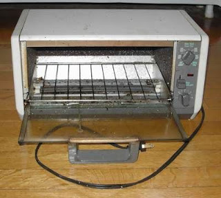
After some time of it sitting unused on the top of my fridge, I decided that I'd take a stab at making it work.
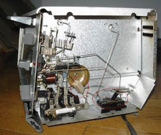
After a few minutes of poking around with a multimeter, I found that one of the safety mechanisms was the culprit (circled in red, at the bottom right of the image below). A lever from the door of the oven was supposed to push open contacts, making sure that the oven wasn't heating while the door was open. This I consider to be a good thing. The problem was that one of the leads on the contacts had blown up... so like any chemist who isn't terribly safety-inclined, I soldered a copper wire around the contact. Not so bad, I thought, since there was still one of the contacts that could be opened by the door. After reassembling the toaster, I carefully turned it on, and when nothing blew up, lit on fire or smoked I was quite happy.
I remained happy for many bagel-breakfasts, until one day the toaster made a quiet popping noise.
This worried me, but the only effect seems to have been it spontaneously turning off.
So once again I popped the oven open, this time determining that there was no flow of current past a component that at one time had been conductive. So I did what any chemist who isn't terribly safety-inclined would, I soldered a wire to bridge around the old component (and subsequently chopped out the non-functional bit). I have indicated this bit in the bottom-right of the image, by drawing a red circle around it.
After plugging in the oven, I once again had that warm fuzzy feeling of a job well done. For about 5 minutes. At which point the oven stopped working again.
Christina, then my girlfriend, was also an engineer. She interceeded at this point, and we decided together that the toaster had reached it's maximum life span (ok, more her than me). It was promptly carried to the front door, to be thrown away.
Soon thereafter, I woke one morning, realizing that I did have a use for the old toaster! I rushed to the front door, and happily found it still there (my girlfriend is much less forgiving about leaving broken things lying around, and I thought it was already toast :p).
This old, broken, already mutilated toaster was going to have a new lease on life: as an SMT reflux machine.
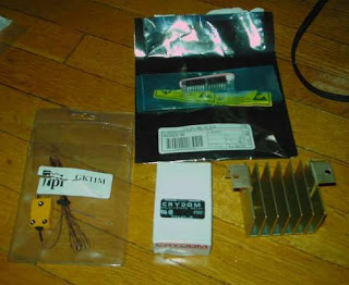
I bought some parts from digi-key (see photo below).
Parts for modifying my toaster oven:
- A K-type thermistor, with 4 foot insulated leads, good to 1000 C. (digikey.ca part number: 290-1911-ND)
- An Analog Devices AD595 Thermoucouple conditioner IC, in a 14 pin dip. (digikey.ca part number: AD595CQ-ND)
- A Crydom 40A 280VAC Solid State Relay, with 3-32 VDC control input. (digikey.ca part number: CC1090-ND)
- A Crydom Heatsink for Solid State Relays from 0-10A. (digikey.ca part number: CC1113-ND)
Why these parts?
The thermistor seems like a good choice for the temperature range needed (according to Kester solder datasheets, that suggest a temperature ramp profile going up to around 225 Celcius). The IC seems to be pretty standard for K-type thermistors, although I could have saved a few dollars by buying an AD597 instead, I figured that I might as well squeeze out the full performance of the really nice thermistor.
What about the relay?
I wanted to be able to control the toaster's resistive heating elements. The bottom of the toaster specifies: 120 Volts, 60 Hz, 1500 Watts. It's a Black & Decker Canada Toast-R-Oven that must be at least 10 years old (manufactured early 90's?). From those power specs I took the guess that if power = voltage x current, then the maximum current for 1500W at 120V (ok, I should use V RMS) is around 12.5A. So I looked at relays, thinking that 15A could be right around the limit of what the toaster could draw, and the 40A relay was only 5$ more expensive than the 25A relay, so I got a 40A... I guess this is overkill, since each of the breakers in my apartment is 15A, and the entire apartment runs off of 2 breakers (no, it's often not enough, and if my desktop is on at the same time as the fridge and the microwave then things get dark. Poor Christine frequently has her cooking interrupted by this.). The heat sink on the relay just seemed like a good idea to me. I figure that the sucker could get hot. Oh the joys of 10$ worth of brass(?).
Ok, so now I have parts sitting around... how am I going to make the controller?
For the last 2 years I have been playing around with lots of microcontrollers. I've used the basic stamp (I even contributed to the linux bstamp utilities), SX chips, and TI's MSP430. Right now I have done lots of small projects with the MSP430. My favorite bit about it, is the embedded 12-bit A/D and HW uart. This means I can just plug in the output of the AD595, and use a digital out to control the relay.
One small problem with controlling the relay from the MSP430 directly: I'm not sure the MSP430 can handle a 35 or 40 mA current on an output pin (it's shown on curves in the MSP430F1610 data sheet... but doesn't explicitly say if the chip will work). The test load in the output frequency tests is 1.5 mA, so I'll take that as a limit. The crydom relay datasheet lists a typical input current of 3.4mA at 5V. Since I'll be supplying it with 3V, it should draw a lower current... hopefully.
I was thinking I'd put an opto-isolator in just in case. I have an old 6N135 opto-isolator around. I've looked up the datasheet, and am surprised to find that the 6N135 draws more current than the relay is supposed to (16mA). Since the optocoupler (optoisolator) also runs nominally at 5V, maybe it's a good thing I'm not using one. Besides, if I'm already willing to attach my computer to a microcontroller via a USB port, and then attach the uC to a toaster over plugged into wall power, I'm being silly to put it an optoisolator to protect the 20$ uC. After all, anything that gets through the relay is going to fry my computer via the USB bus anyways (and anything else powered through its 5V bus). I'm thinking Christine will already have the fire-extinguisher in hand when I plug the oven in the first time ;).
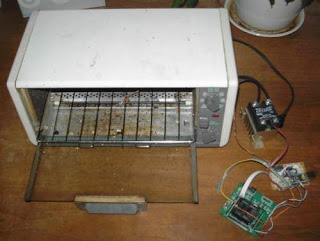
To the right of the oven (moving counterclockwise from bottom-right) are the uC, serial-USB converter and power supply board, relay, power cord, and inside the toaster oven (right in the middle) is the thermocouple (tied in a knot around the grill).
Ok, so I tried that, and it didn't work too well... in fact, the relay pretty much seemed to completely ignore anything the microcontroller told it to do. Instead, I've been told by greater people than I that I should use a 2n7002 transistor to switch the toaster on/off. Pretty easy, and I bought the transistor, even soldered it (a 3 pin SMT component), but I haven't thrown it into the circuit because I have since unplugged things and need to re-wire/re-program the uC (microcontroller). I do have the C-source for the microcontroller, but I don't remember the exact wiring set-up I had going on.
What I had done, was to manually switch the oven on and off... I realize it's non-ideal, but at least I can tell what temperature the inside of the oven is, within about 1 degree Celcius (and if the thermocouple is placed directly touching the PCB, that means a pretty good idea of how hot the PCB and components are.
Using the manual on/off method, I ran a few test runs to determine if it was possible to measure the temperature ramping rate (data file 1 and data file 2, contain the raw output from a serial port capture). One thing to note was the fact that I hadn't yet figured out how to properly determine the bitmask for the HW serial port on the uC. More recently, data comes out in a much cleaner, less error-prone format.
Finally, I ended up using the oven a few times in my lab at McGill to solder some REALLY fragile 6 and 8-pin TAOSinc light to frequency sensors onto proto-PCB's from digikey. It worked quite well...
This week I'll try to get it going again, using the actual 2n7002 transistor to switch the oven. I'll also try to get it going from my G5. Wouldn't that be sweet: a G5-powered lead-contaminated toaster oven.
UPDATE (April 2006): Well, the previous sentence isn't quite accurate. It has been over 1 1/2 years since I last worked on my toaster oven reflux project. I still have to finish installing and finalizing the circuitry. Now that I have a milling machine with which I can mill PCB's, I think I'll finish this project.
The main obstacle to using the CNC toaster over as a reflux machine has absolutely nothing to do with the functionality of the temperature control... Rather that toaster oven grills are not at all made to be stably moving platforms. They are rather jerky in their motions. So when a PCB is carefully placed on the metal grill, it tends to bounce around a bit. This bouncing displaces the small surface mount parts from where they should be soldered in place, and renders the reflux oven much less useful.
When I do build the proper circuit, this time I will make sure that I fix the grill problem. I'll probably use some angle brackets from home hardware to build a small, stable platform on which to place the circuit boards. I'll try to make it a softer surface, so that no shocks can bounce things around. I'm not sure what materials to use that will both serve as shock absorbers and survive the fairly high temperatures involved... if you (the reader) have any ideas, please send me a note... :D [francis at esmonde-white dot com]. Thanks!
UPDATE (December 2010): Clearly I haven't made much progress with this project. I'm actually a few step backwards now. When I moved to the US, my wife (Karen) was quite adamant that the demented toaster oven not come with me. I still have the controller bits, but I'll need to get a new oven at some point.